Multimeter Repair Sanwa CD720-C
31/08/2020
An account of my repair of my old Sanwa digital Multimeter
Warning!
Although this relates technical matters which may be beyond the experience of the average reader,
I have attempted to write so as to interest such a reader.
Technically-minded readers will have to put up with explanations
of matters which may seem obvious to them.
What was wrong?
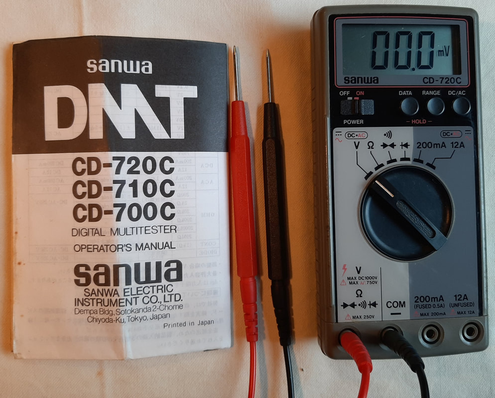
In the course of testing a guitar lead for noise, I found my Sanwa digital Multimeter was unusably faulty. I had to resort to digging out my old (model discontinued pre-1980) Hioki analogue meter.
The dial with needle-type analogue display is perfect for testing a noisy lead, because you can see how far and how quickly the needle jumps, whereas a digital display just shows a lot of rapidly changing numbers, which are not as easily interpreted.
I was able to see clearly that the lead was faulty, and also resolved to buy a new digital meter to replace the Sanwa. Once I had bought a new meter, and realising I now owned three different Multimeters, I thought it was worth creating a blog entry about them.
(See my previous blog post: - Multi-Multimeters)
|
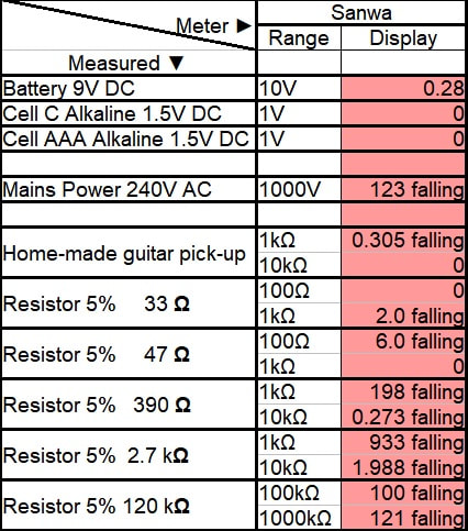
In the course of making a range of comparative measurements with all three meters for that blog post, I confirmed just how bad the readings from this Sanwa meter were.
The fault causes incorrect readings that slowly fall, see the test measurements highlighted in red at Left. I had initally thought that as the meter depends on an inscrutable and impenetrable integrated circuit, and there is nothing untoward visible on the circuit board, and no capacitors look swollen (a common fault), the actual fault would be hard to find. That is why I just went and got a new one. However, as I am not getting out much during the current situation I thought as something to do at home I might document an attempt to find and fix the fault. What follows below is the result of my repair attempt. |
What is the Fault?
Back cover off
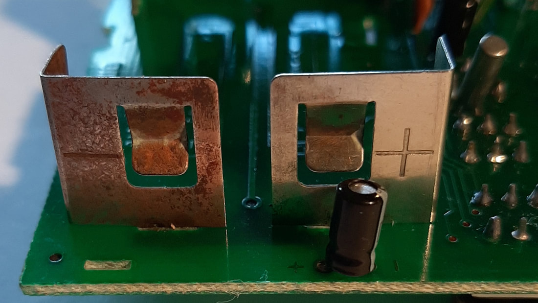
Cell holder terminals corroded
Front cover off
|
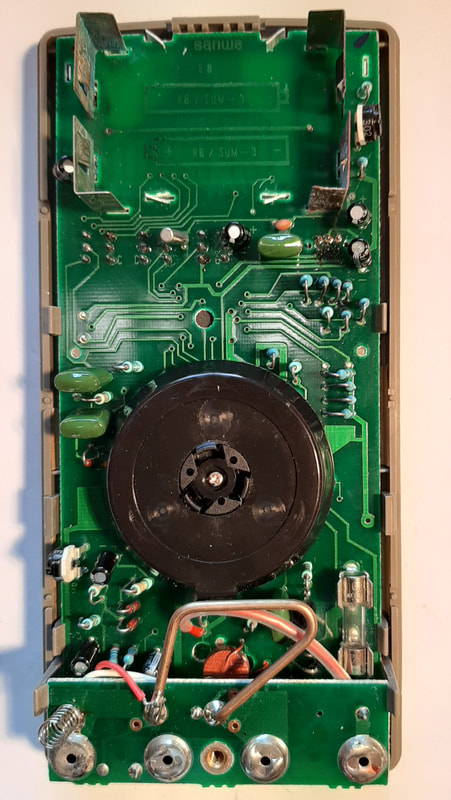
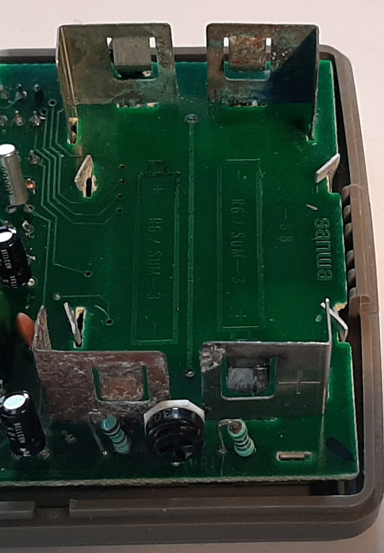
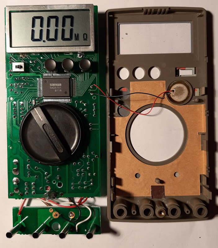
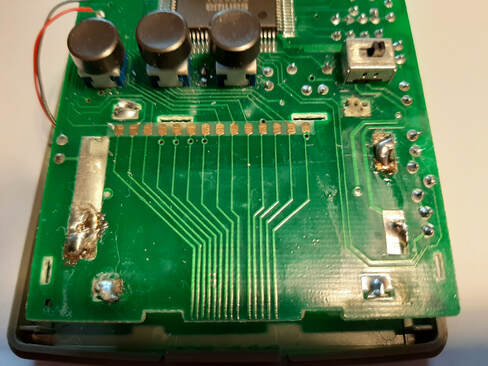
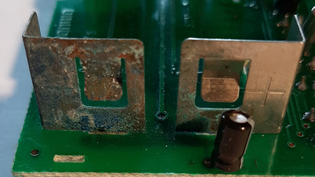
With no circuit diagram and the documentation a single folded sheet of user instructions, I took the approach of just opening the thing up to see what could be seen. First off, we see what I will call the back of the main circuit board, which is held within the case by some plastic flanges at its edges. On the board are a large range-selector switch, some resistors, capacitors and diodes, and a set of holder terminals for the 1.5v cells. At one end there is a smaller sort of mezzanine level board which holds connections to the large terminals where the test leads plug in. There was no obvious damage such as cracks, melts or burns that might cause both voltage and resistance readings to be wrong. However, as I remarked in the comparison blog, "The cell holder terminals are a bit corroded, as I had some cells go bad once. I am suspicious that there might be some damage I can't see that has finally made it go faulty." See the next pic for a closer look at the terminals. At Left we see both corrosion and a tinge of blue where there are still actual sulphate crystals on the terminals. Who knows whether any of these crystals have flaked off, where they might have ended up, and what they might do to the circuit of the Multimeter? This is decidedly dodgy stuff, and even if there was no fault it would need cleaning up to prevent one developing. I am quite surprised to see it, as I vaguely recall cleaning up as best I could at the time I had some cells go bad. Evidently my clean-up looked OK, but didn't cope with invisible chemicals still present. What is also concerning is that within the cell-holder area of the circuit board we see four bent aluminium flanges holding the mount of the Liquid Crystal Display (LCD) module, which connects to the front side of the board directly above the potentially crystal-shedding cell terminals. It is definitely worth extracting the whole circuit board from the case and having a good look at the other side. Here we see the other side, which I will call the front, of the main circuit board. Mounted on it is the Integrated Circuit (IC) with its tiny pin connectors to the board, and the user interface components: the rotary range-selector, a little On/Off switch, three display control buttons, and the LCD module, surrounded by its aluminium mount. There are also two red and black wires to the continuity test beeper of such high frequency I can no longer hear it, which is mounted on the back of the face I thought the IC was likely to be common to both voltage and resistance measurements (well, all measurements really), and that if the fault was in there, there was no hope of a repair. The display seems to be undamaged; no dead segments, no flickering, no faintness. We can expect that any inaccuracy is in what is sent to the display, not the display itself. However, with all that corrosion so close to it, I feel it is worth trying to unmount the display to check there is no dirt, corrosion or crystals interfering with the signals going to it. |
|
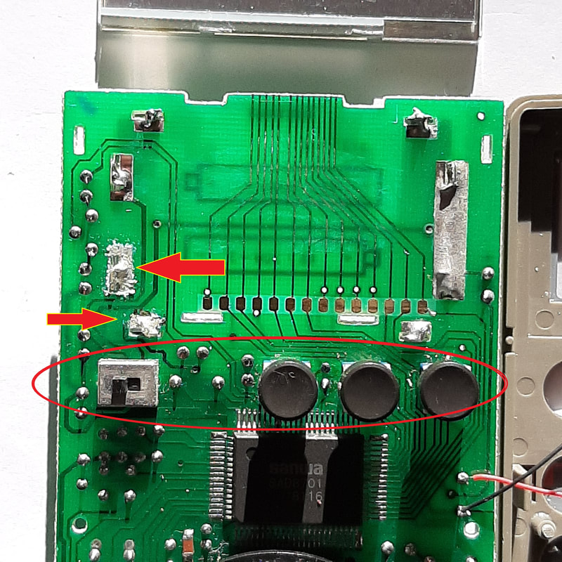
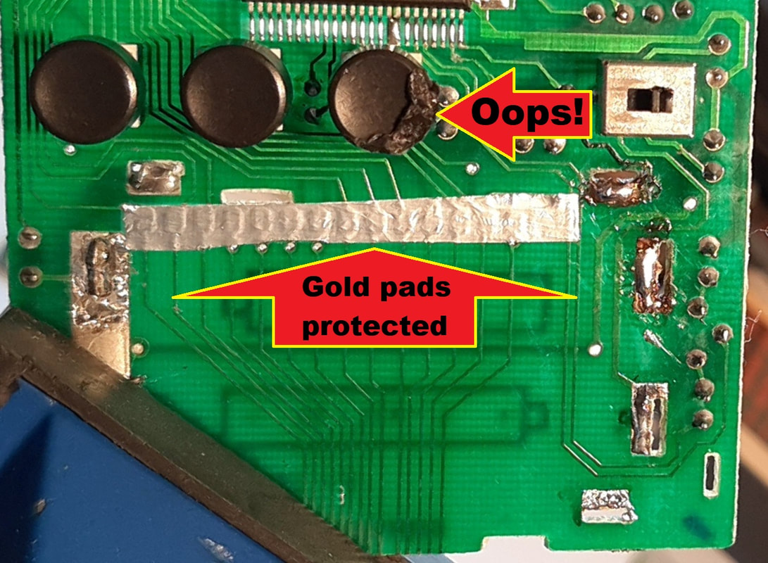
Underneath the display module is not a pretty sight. Even the lead-based solder which both connects to and holds in place the cell holder terminals has crusty white crystals on it. (Red arrows, Left) This will probably be lead sulphate, as that is white, crystalline, and also toxic and corrosive, especially to the eyes. Nasty, but a tiny amount.
Also, on the board, more noticeable in the area of the red oval, there are a lot of indeterminate specks and particles. This is in the area under the holes in the face for the buttons and power switch, so they could just be dust that has fallen through. Nevertheless, things need cleaning up. Happily, the row of gold (Yes, real gold!) pads on the board which connect to the display appear clean and shiny. |
LCD back with Elastomeric connector
Elastomeric connector close-up
Elastomeric connector close-up - different lighting
|
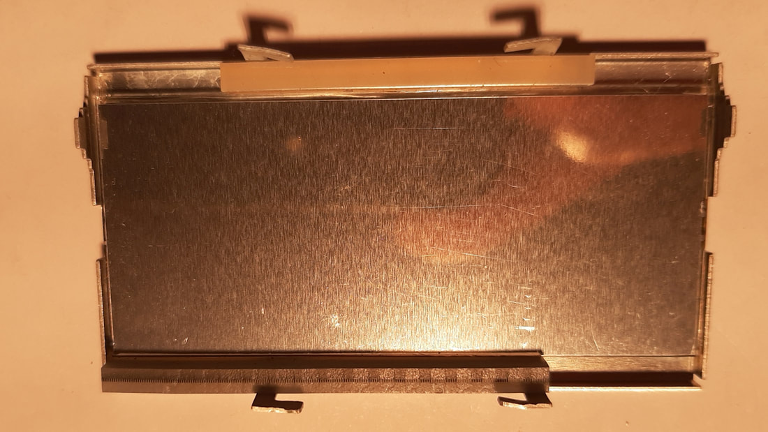
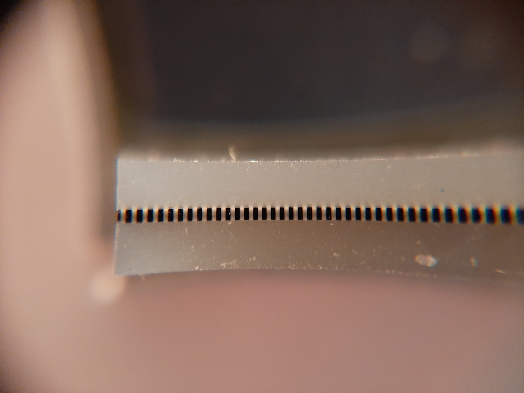
Turning to the back of the LCD (Left), we find quite an unusual method of connection from the board to the display. (Perhaps not so much unusual, as unfamiliar to me!) Aligned with the row of gold pads on the board is a rubbery strip with a faint lined pattern on the outer face. However this works, I am sure anything getting between the strip and board is not a good idea. I did a bit of searching and found the rubbery strip is called an elastomeric connector. A close-up of my one (Left) shows the ends of tiny conductive channels which pass from the outer face through the (probably silicone) rubber in a parallel row to connect with the thin and fragile glass of the LCD itself. At Left, up close under different lighting, we can see the marks made on the elastomeric connector by the extra pressure from the raised gold pads on the board. We can see that five channels touch each pad, then six sit in the gaps. This shows how the connection method gets around having to be precisely aligned with the gold pads. As long as the connector is aligned widthwise within the size of the pads, and lengthwise within two or three channels, it will work fine. |
Conclusion: -
In the absence of any other evidence, at his stage the working hypothesis is that partial short-circits from corrosion crystals and/or dirt, and possibly poor connections to the LCD are the cause of the fault.
In the absence of any other evidence, at his stage the working hypothesis is that partial short-circits from corrosion crystals and/or dirt, and possibly poor connections to the LCD are the cause of the fault.
Can it be repaired?
There is very little risk in undertaking a general clean-up of the board and connections
to at least see what effect we can have on the Mulitimeter's functioning.
Conclusion: - We'll give it a clean and see what happens!
to at least see what effect we can have on the Mulitimeter's functioning.
Conclusion: - We'll give it a clean and see what happens!
Repairing the fault
|
The whole back and front of the board (The green surface) was cleaned of particles with a few cotton buds soaked in methylated spirits.
The solder connections to the cell holder terminals were cleaned and re-soldered. The row of gold pads and the elastomeric connector face were cleaned with methylated spirits. The LCD module was refitted, the cells were put back in, and while the Multimeter was still open, some readings taken. The cleaning had made a slight difference, but not enough to make the instrument anywhere close to usable. Although the resistance readings were now more accurate, they were still not good enough, the voltage readings were still inaccurate, and all still showed the slow falling readings as well. |
 Sanwa Quad Flat Package SAD8701 pin close-up
I then noticed that if my finger touched the IC, the resistance readings would drop by up to half in about a second, then return to normal after about a minute.
To see if this was a temperature related thing, I tried fanning the IC after touching it, and this did cause a quicker return to normal.
Trying to confirm the temperature hypothesis, I found breathing on the IC would cause a really massive drop in the reading. This was a bit puzzling, as I would have thought a direct contact from a finger would heat the chip up much more, and faster than a bit of warm air flow. Fanning the IC after breathing on it also caused a quicker return to normal.
I tried putting a soldering iron close to the IC, but this made no difference. I then tried using my heat gun to blow hot air on the IC, but that made no difference either! Very strange.!
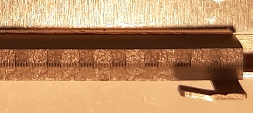
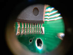
After a bit of thought, I wondered if there was still some residual sulphate or dirt between the very tiny pins from the IC to the circuit board. These are only spaced at about 0.75 mm (See Left).
If this stuff became conductive only when moist, it would explain why breathing but not heat affected the readings, and why fannning the IC would cause a quicker return to normal: through evaporation.
I got a thin sheet of packing foam and used it to shield the IC while breathing on the rest of the board. No effect. Including the IC made the effect return. In fact, I isolated the effect to just the row of pins nearest the range selector switch!
I got out the methylated spirits and cotton buds again, cleaning that row of pins, and then all pins on the other sides as well for good measure.
Now the slow falling readings had entirely ceased. The resistance readings were now far more accurate but not as good as desired, and the voltage readings were still slightly low.
However, I would get good steady readings at a session, but when I carried on at another time, to make a final set of readings, the readings would be different, although not by much. Very mysterious.
To see if this was a temperature related thing, I tried fanning the IC after touching it, and this did cause a quicker return to normal.
Trying to confirm the temperature hypothesis, I found breathing on the IC would cause a really massive drop in the reading. This was a bit puzzling, as I would have thought a direct contact from a finger would heat the chip up much more, and faster than a bit of warm air flow. Fanning the IC after breathing on it also caused a quicker return to normal.
I tried putting a soldering iron close to the IC, but this made no difference. I then tried using my heat gun to blow hot air on the IC, but that made no difference either! Very strange.!
After a bit of thought, I wondered if there was still some residual sulphate or dirt between the very tiny pins from the IC to the circuit board. These are only spaced at about 0.75 mm (See Left).
If this stuff became conductive only when moist, it would explain why breathing but not heat affected the readings, and why fannning the IC would cause a quicker return to normal: through evaporation.
I got a thin sheet of packing foam and used it to shield the IC while breathing on the rest of the board. No effect. Including the IC made the effect return. In fact, I isolated the effect to just the row of pins nearest the range selector switch!
I got out the methylated spirits and cotton buds again, cleaning that row of pins, and then all pins on the other sides as well for good measure.
Now the slow falling readings had entirely ceased. The resistance readings were now far more accurate but not as good as desired, and the voltage readings were still slightly low.
However, I would get good steady readings at a session, but when I carried on at another time, to make a final set of readings, the readings would be different, although not by much. Very mysterious.
Terminals still corroded Left
Terminals still corroded Right
Desoldering terminals in progress.
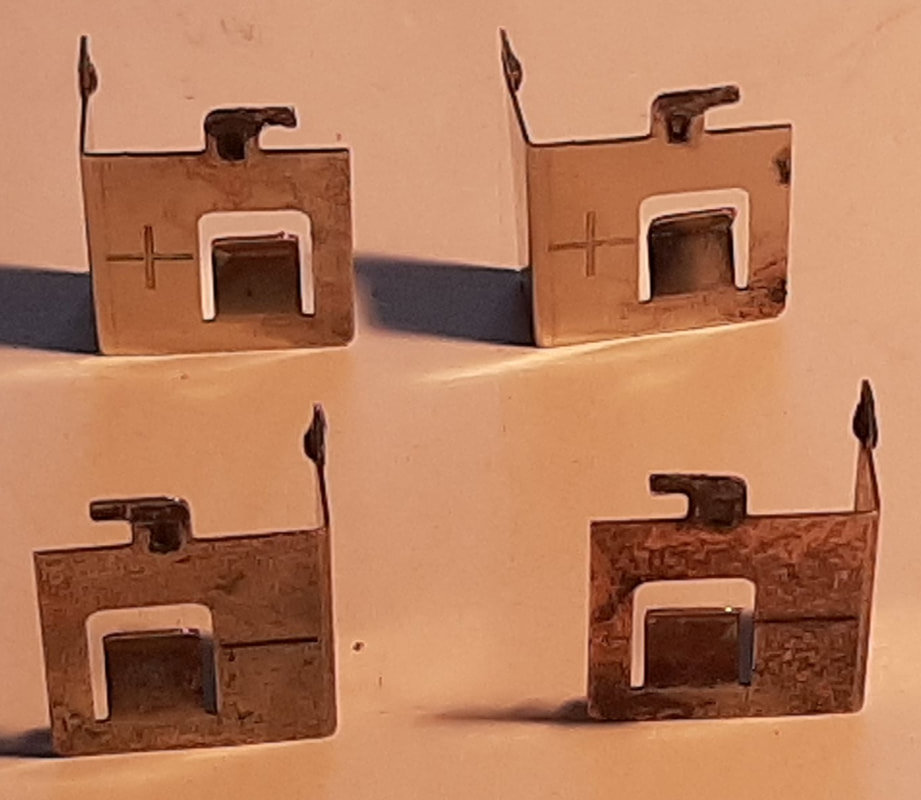
Terminals acid treated and polished
LCD mount area - terminals resoldered
Terminals cleaned & refitted Left
Terminals cleaned, repaired & refitted Right
|
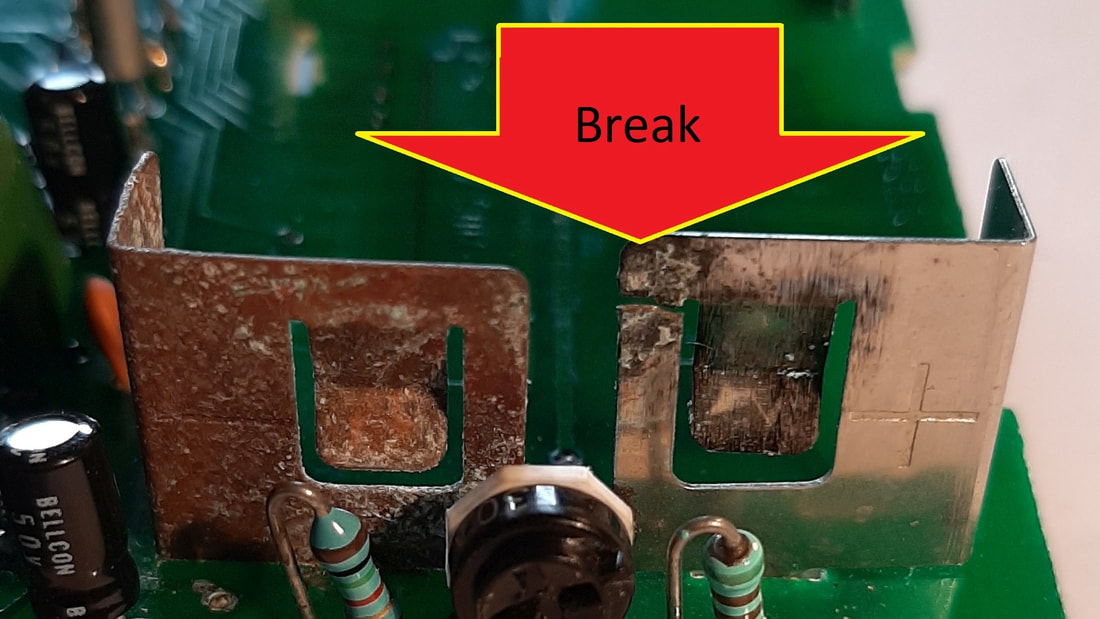
After a week's hiatus, and some more thinking, I decided that I was not in the clear in the corrosion department. Although they weren't obviously flaky, there was still corrosion colouring the cell-holder terminals, and one had even got weak enough to break during my repair activities. I decided the best way to deal with the corrosion was to remove the LCD module again so as to remove the terminals entirely from the circuit board, and also to clean the cell-holder area more thoroughly while the terminals were removed. The gold pads which connect the LCD, being so close to the terminal mounting tabs needed protection during the desoldering. Gold is used because it doesn't oxidise, but that property is precisely why it needs protection. Any solder splash will likely bond immediately and irrecoverably to the gold,ruining its good connection properties. The protective solution I came up with was a double layer, with aluminium foil stuck to some double-sided Sellotape and then both cut to fit over the pad area. (See Left). Pity I never thought of protecting the plastic selector buttons, one of which I managed to melt with the soldering iron. I never cook with white vinegar, but I keep a two litre bottle for other purposes. Cleaning up corrosion is one. My removed terminals were fully immersed for a few hours, which dissolved all traces of the sulphate. After a good rinse in tap water (locally pH is 7.6 :-), there was still a little surface discolouration, so I applied a little elbow grease assisted by Brasso™, another very handy cleaning aid. This produced the result pictured at Left. While the terminals were in the vinegar, I cleaned the cell holder area as planned, then while waiting I used my other Multimeter to check all the diodes and a few resistors and capacitors on the board I thought worth testing, finding nothing untoward.
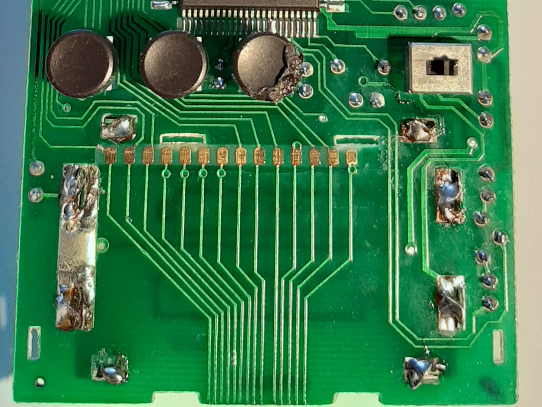
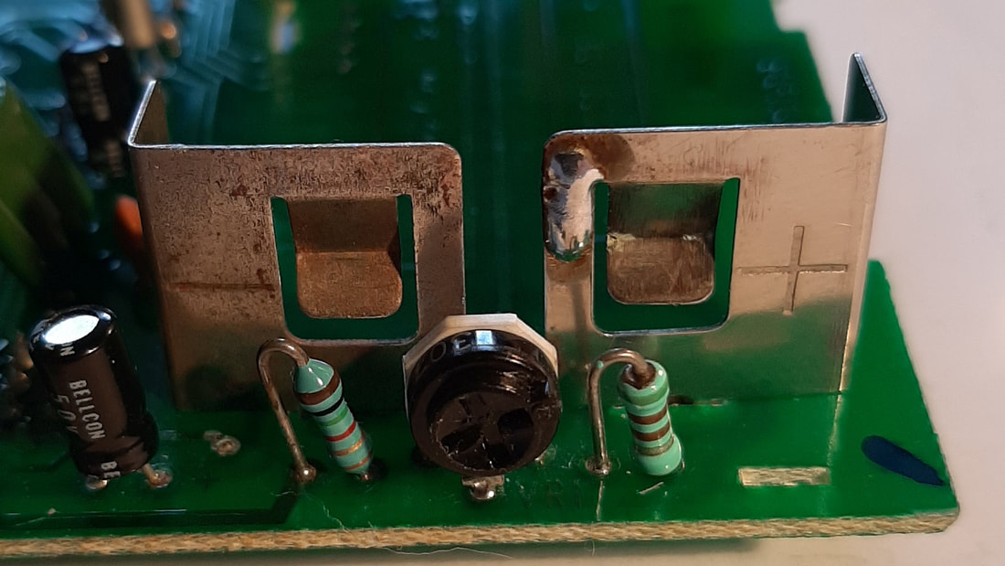
After re-coating their little L-shaped tabs with solder, the terminals were reinstalled on the board and their tabs bent to secure them in place. The tabs were then resoldered to the circuit board and the protection removed from the LCD connector pads (see pic at Left). After this pic was taken I gave the area a good clean-up with methylated spirits again to remove any remaining solder flux, then cleaned all the board again, both sides, and all the IC pin connector area again. The board with the cleaned-up terminals in place is now looking more as it should. The pix at Left, when compared with the "Terminals still corroded" pix above, show a great improvement. I repaired the break in the Right positive terminal with solder before re-fitting it. Solder is certainly strong enough for such thin metal as this. |

It was now time to remount the LCD in its holder, refit the cells, and take a few readings with the Multimeter to see how it was now behaving.
I found it was reading pretty much correctly and there were no falling readings. Touching or breathing on the IC had only a small effect. However, if I left the Multimeter overnight and retried again the next day, the readings were close but not the same.
After giving this some thought, I checked the Specifications in the user instruction sheet (See Left).
Sure enough, I found the temperature tolerance lower limit was only 18°C. I had been causing reading differences by taking readings at different temperatures on different days.
I have been working from home, and had made a habit of rechecking the readings in the morning before starting work. It is winter here, and the temperature at the repair desk was usually well below 18°, as low as 10 or 12°, whereas I was often working on the repair and taking readings after finishing work at 15:30, when it was much warmer, around 21° or higher if sunny.
After confining my reading checks to a few afternoons only, I was now happy that the Multimeter was behaving well and consistently.
Before reassembly I repaired the button I had melted. The button could be popped off the switch underneath, and a small file was used to take off the excess squished plastic so the button would fit back through its hole in the face of the case. A black felt pen served to match the colour of the filed area.
I also had to resolder the red and black wires to the continuity test beeper of such high frequency I can no longer hear it, the wires having broken off with handling during the repair work
Testing the repair
There was no physical repair to test. All that remained to be done was
to mount the circuit board back in the top of the case, and fit and screw on the base.
to mount the circuit board back in the top of the case, and fit and screw on the base.
Final Results
|
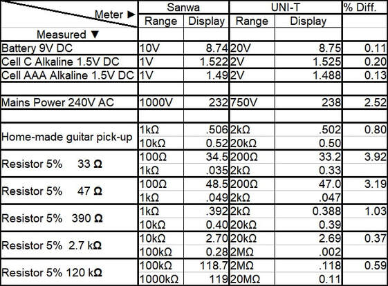
After reassembling the Multimeter I repeated the tests I did for the previous Multimeter comparison blog.
The results (Left) were extremely gratifying. All readings are steady once the IC has decided what to display. The Resistance tests are now returning readings different by only 1% or less from the new digital Multimeter, excepting the 100Ω range, which is nearly 4% different. The errors seem to decrease as the range gets higher, which is interesting. The voltage readings are great at one or two tenths of a percent different, except the mains AC reading but even there, the difference is only 2.52%. |
I would rate this little Multimeter
still pretty much as good as new.
Not bad for an instrument
over thirty years old!
still pretty much as good as new.
Not bad for an instrument
over thirty years old!
