Multimeter Repair Hioki TX-20
23/08/2020
An account of my repair of my little old Hioki Multimeter
Warning!
Although this relates technical matters which may be beyond the experience of the average reader,
I have attempted to write so as to interest such a reader.
Technically-minded readers will have to put up with explanations
of matters which may seem obvious to them.
Warning!
Although this relates technical matters which may be beyond the experience of the average reader,
I have attempted to write so as to interest such a reader.
Technically-minded readers will have to put up with explanations
of matters which may seem obvious to them.
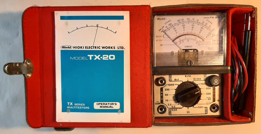
Hioki TX-20 Multimeter, Pre-1980
What was wrong?
In the course of testing a guitar lead for noise, I found my Sanwa digital Multimeter was unusably faulty. I resorted to digging out this old (model discontinued pre-1980) Hioki analogue meter. I must have used it recently, as it wasn't stored without cells, and the two 1.5v cells in it were in a good state of charge.
The dial with needle-type analogue display is perfect for testing a noisy lead, because you can see how far and how quickly the needle jumps, whereas a digital display just shows a lot of rapidly changing numbers, which are not as easily interpreted.
I was able to see clearly that the lead was faulty, and also resolved to buy a new digital meter to replace the Sanwa. Once I had bought a new meter, and realising I now owned three different Multimeters, I thought it was worth creating a blog entry about them.
(See my last blog post: - Multi-Multimeters)
|
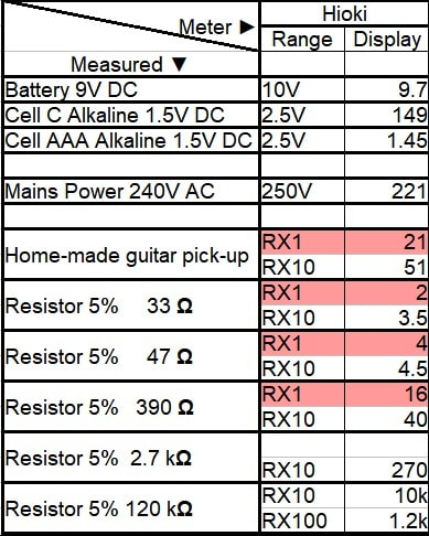
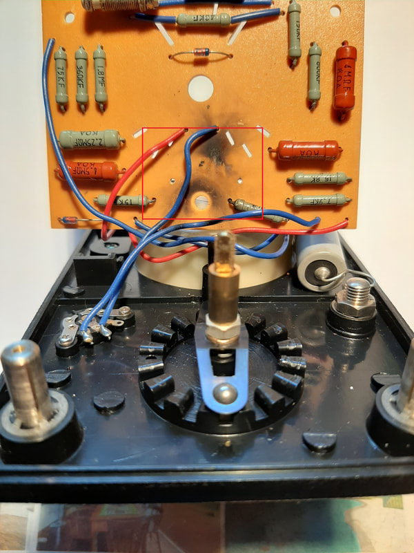
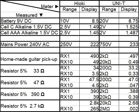
In the course of making a range of comparative measurements with all three meters for that blog post, I found this Hioki meter was reading very low, but only on the RX1 scale.
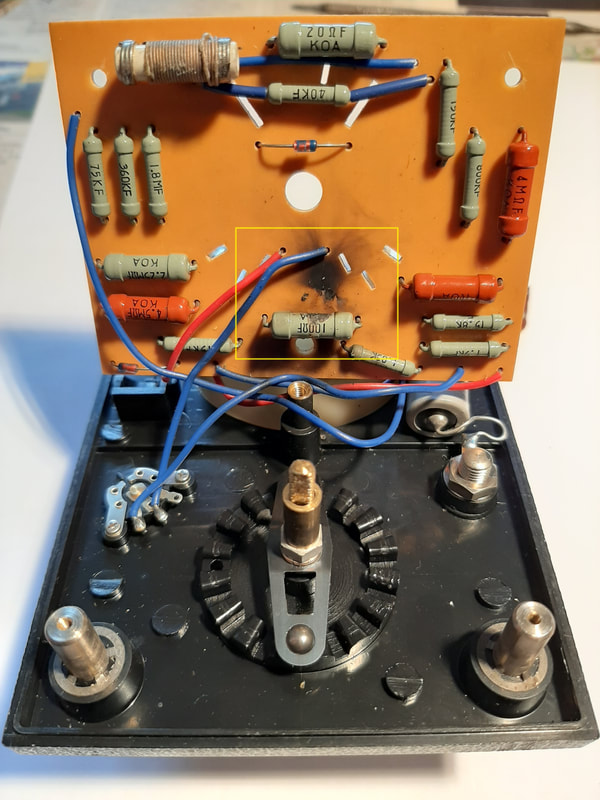
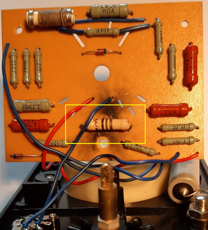
(See the measurements highlighted in red, at Left) I am not getting out much during the current situation; as something to do at home I thought I might document an attempt to find and fix the fault. The process was made much easier by Hioki helpfully supplying a circuit diagram and parts list with the Multimeter, not something we see with many products these days! What follows below is the result of my repair attempt. Note: - I will use the term "Multimeter" to refer to the instrument as a whole, and the term "meter" to refer to the little indicator dial unit with the moving pointer. |
What is the Fault?
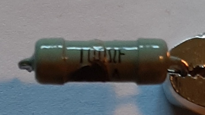
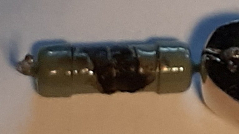
Blackened & no longer 100Ω resistor
|
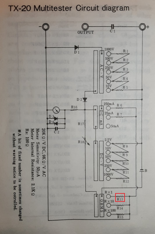
The first fault-finding clue is the fact that only one of the three resistance ranges is faulty. Thus, we need to find what parts of the Multimeter are particular to the RX1 range.
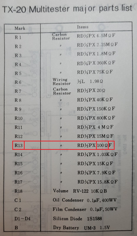
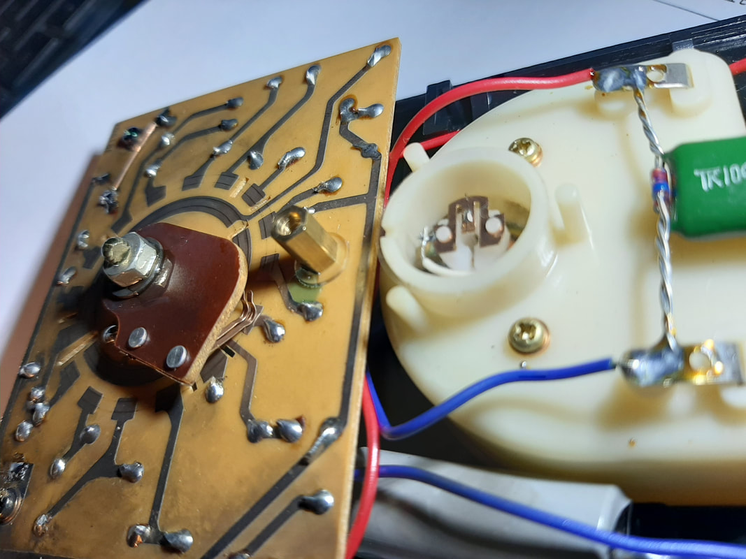
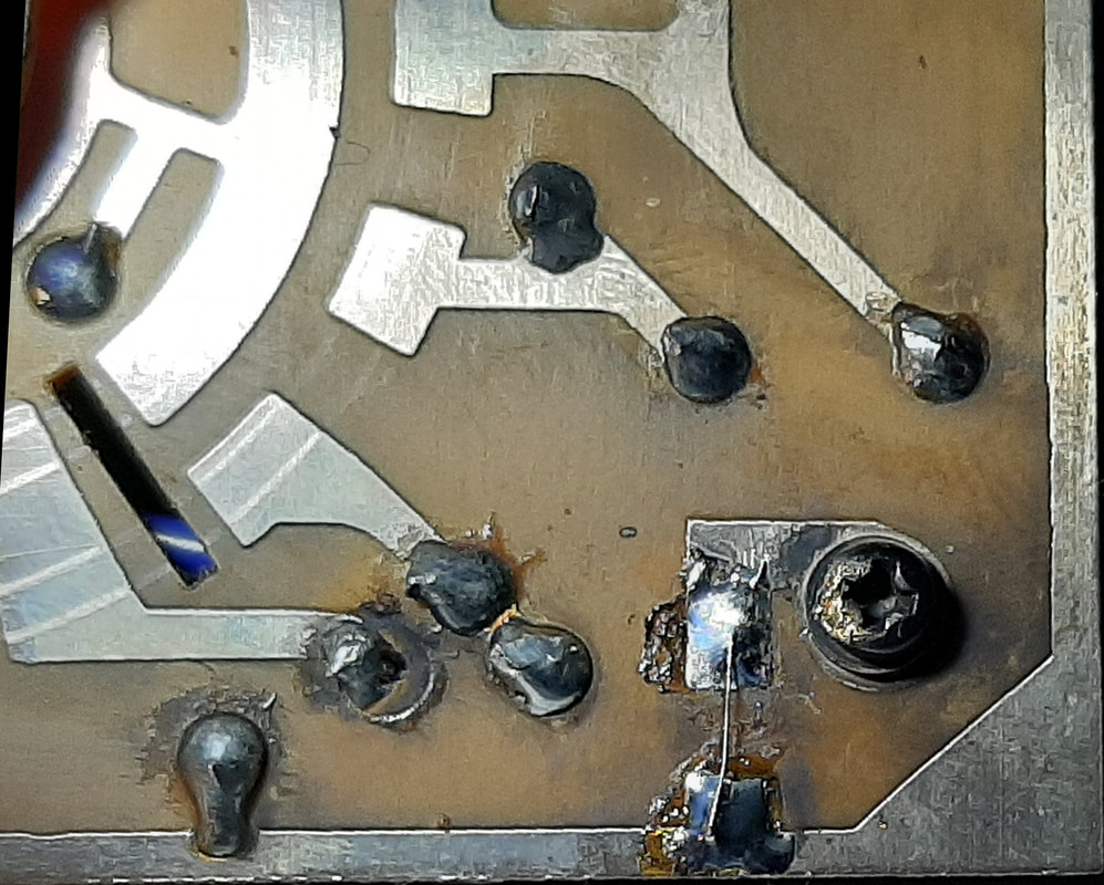
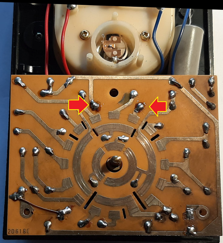
The Multimeter has to have different range settings because of the limitations of the meter mechanism which indicates the readings by rotating clockwise in proportion to how much current flows through it. The meter cannot both be sensitive enough to respond to a tiny measurement, and also cope with a large measurement. That is, there is a limited range of electric current which can usefully and safely flow through it. Measuring a high resistance will involve that resistance limiting how much current can flow through the meter. Measuring a low resistance approaching zero will result in a maximal amount of current being able to flow through the meter. Given that we are limited to 3 volts from our two cells, we need to arrange the Multimeter's circuit so that there is always a suitable internal resistance to supply enough or prevent too much current through the meter on each of the ranges. This is done by what is called "shunting" the current around the meter. This old railway term is used to describe creating a path parallel to the one the meter is on, which can carry current around and past the meter, just as a shunting engine can move carriages about on other tracks in a railway yard. In the circuit diagram at Left, at lower right we see three zig-zag lines labelled R13, R14, and R15, each connected to little circles representing switch contacts which are labelled R x 1, R x 10 and R x 100. The zig-zag lines represent resistances, and they are the shunt resistances for our different ranges. A check of the parts list at Left, shows that, of the three shunt resistors, R13 has the lowest value. This is because when you measure a low resistance, a high current could flow through it, so we need a low resistance shunt to allow most of that current to bypass the meter. Conversely, R15 has the highest value because when you measure a high resistance, a low current will flow through it, so we need a high resistance shunt to keep most of that low current directed through the meter. Because there is only one shunt resistor for each of the three ranges, and no other parts change when we change ranges, we can conclude that the only part of our Multimeter circuit that is different when we make the RX1 measurement is R13 in the red box. Now, my fault is that the RX1 range is reading too low. This means that the meter is receiving a high current and moving fully to the right, where the zero reading is. Therefore, too much current is going through the meter, and not enough, or none, is being shunted by R13. We can conclude that R13 has gone high resistance, or is even disconnected, or "open circuit". Our next step therefore, should be to find, examine and measure this R13. On removing the back of the Multimeter we find the back of a circuit board with a roughly circular pattern of copper on it (See Left), and at the centre of the circle, a rotating arm attached to a shaft which has the front rotary range selector on the other end. The arm has springy metal bits called wipers, which move around the board, making different parts connected for different ranges. Basically, this is called a rotary switch. When we set the selector on the front to RX1 and look at the circuit board, we can easily see which positions on the board are being connected by the switch wipers. (In the pic at Left, the wiper is indeed at the RX1 position.) Now, if we look underneath to see the "front" of the board, to see what parts are attached at those positions, lo and behold we are presented with the sight at Left; a decidedly dodgy-looking little grey-green cylinder with a blackened underside. Although partially obscured by a blue wire, it appears to be labelled 100Ω. To me, this provided near enough to 100% certainty that the fault had been located as a damaged 100Ω shunt resistor, R13. A quick check with my fancy new digital Multimeter showed that R13 was indeed "open circuit", or to put it colloquially, buggered. This may seem like a long-winded procedure, but IRL there was no need to explain anything, and I took less than 2 minutes to find the fault. |
Can it be repaired?
The resistor is in a gap between meter face and cct board
There is a switch shaft thru the face and cct board
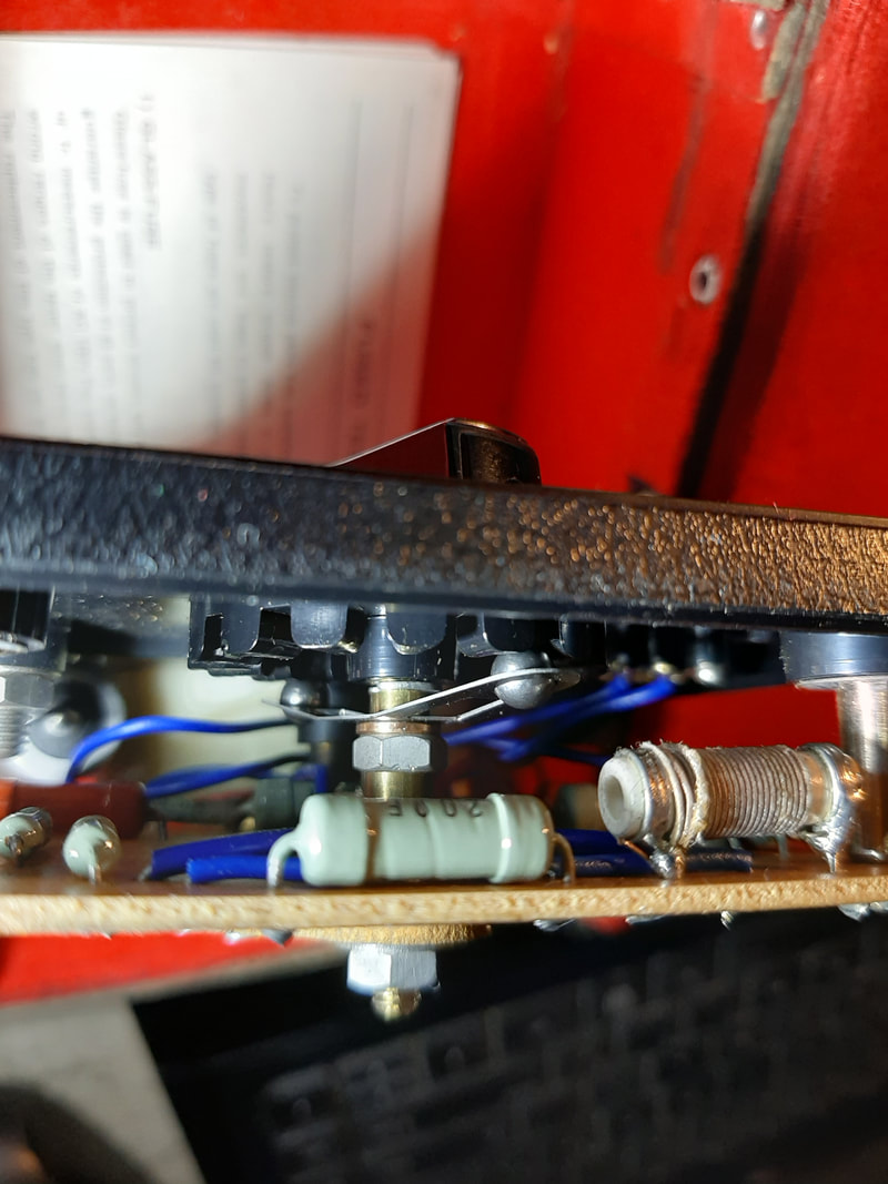
The switch has a ball & spring detent to hold it stopped at each selected position
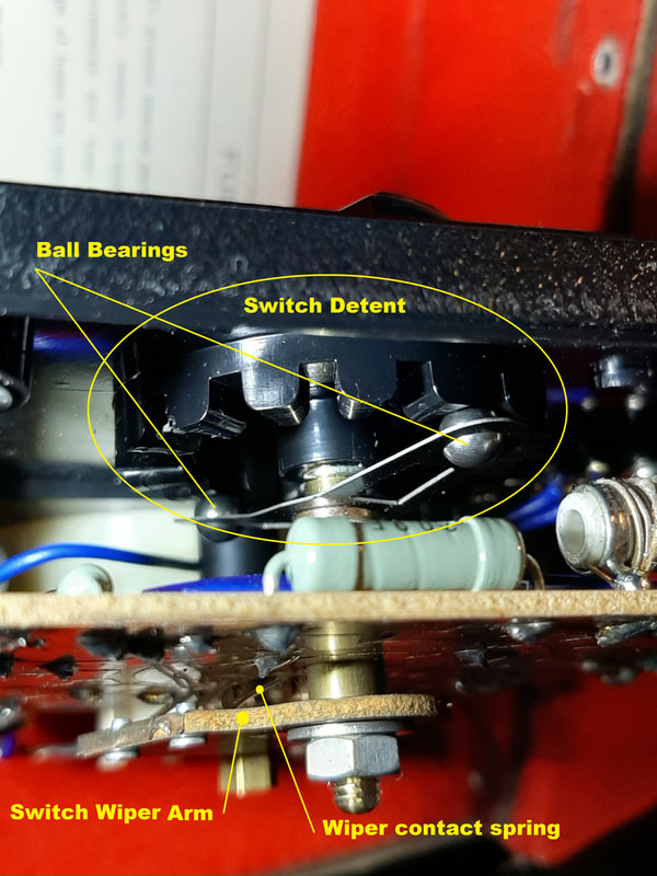
The switch wiper arm is on the other side of the board
|
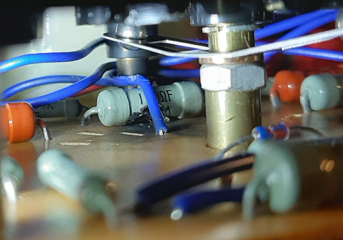
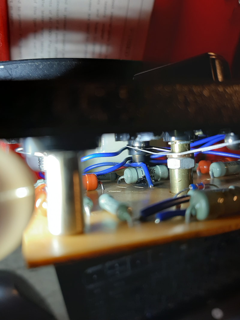
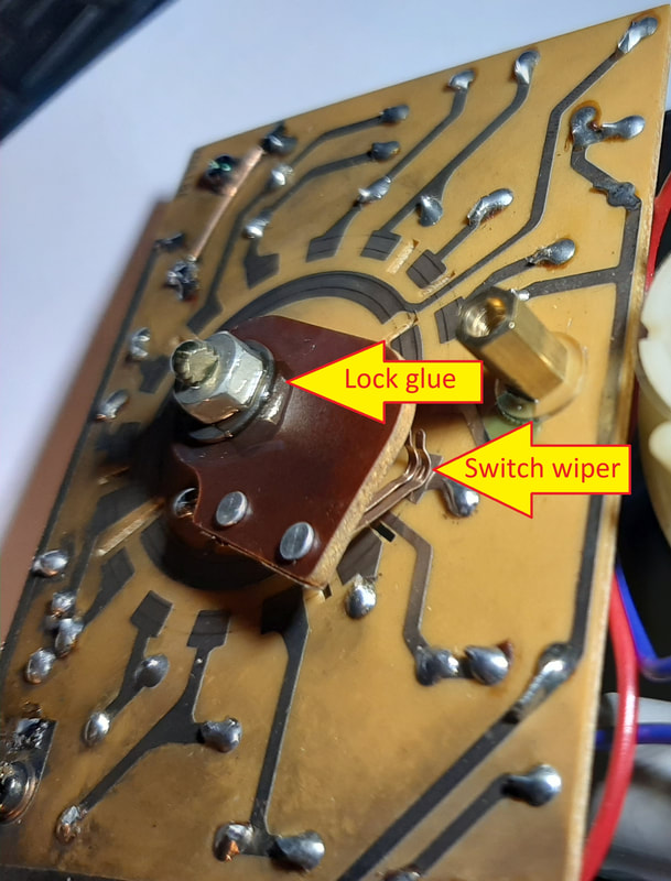
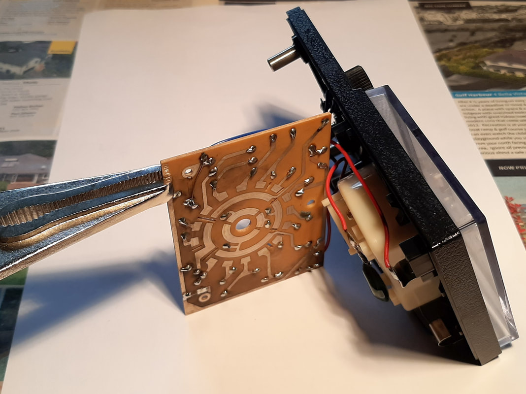
Now that the fault is located, we must decide if it is worth the effort of repairing. First, there is the question of access. If we pull back a little we can see that the "front", or component side of the board is mounted facing the underneath of the Multimeter's top face. Thus, if we are to get at the resistor to remove it, and then install the replacement, we are going to have to somehow separate the board from the Multimeter face. Pulling back a little further we see that the shaft from the range selector passes through the face and the circuit board to hold and rotate the wiper arm. The wiper arm is going to have to come off to let the board come away from the face. Worryingly, there is also some kind of mechanism mounted to the shaft inbetween the face and board. Is that going to have to be disturbed as well? ] If we change angle a bit we can see the switch shaft has a couple of springy arms which each hold a little metal ball against a slotted disk attached to the face. This is what would be called a spring detent, which holds the shaft reliably in place, stopped accurately at each selected position. The last thing we want to do is start disassembling to get at the board front, only to find little balls and springs flying off in all directions, which require a special assembly jig, and the nimble fingers of a young Japanese factory worker to reassemble those parts not lost. At Left we can see the detent's balls and springs, as well as the wiper arm with its nut holding it to the shaft. This nut we will need to take off to allow removal of the board. It appears that the detent springs are actually two ends of a single flat stamped sheet which the shaft passes through. The spring is held safely in place against the face by a nut on the shaft sitting between the board and face. The nut is clearly visible in the previous pic. Thus, if we take the board off, the detent mechanism will stay safely intact. Phew! |
What caused the fault?
The fuse wire is on its third stapling. Hmmmm!
Fuse wire has been replaced, also the cct board mounting screw looks melt damaged
Positive test probe melt damage
|
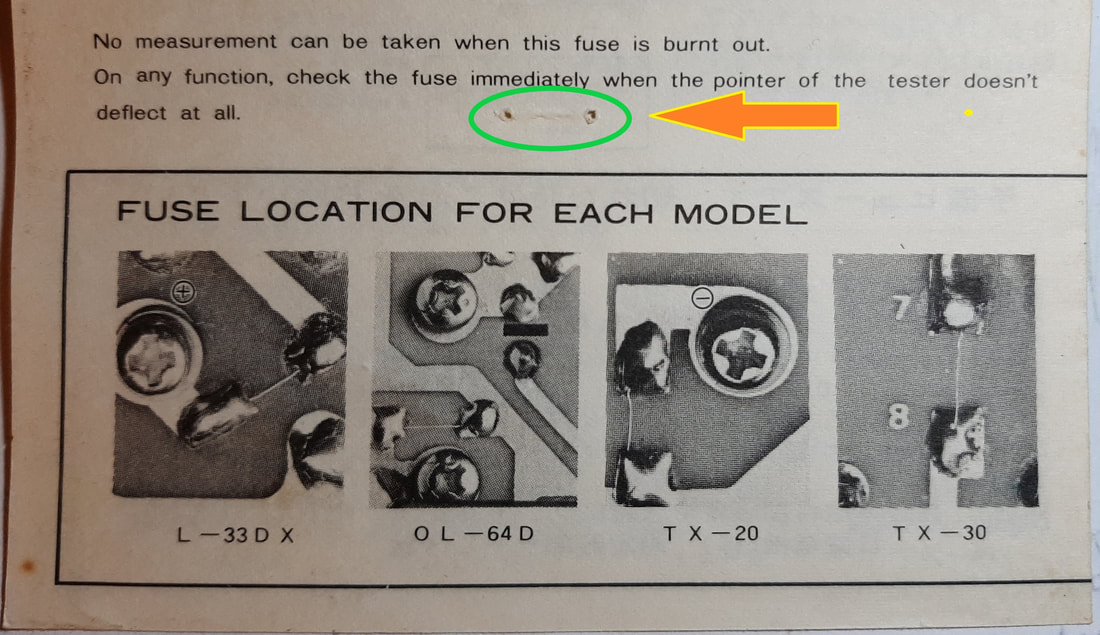
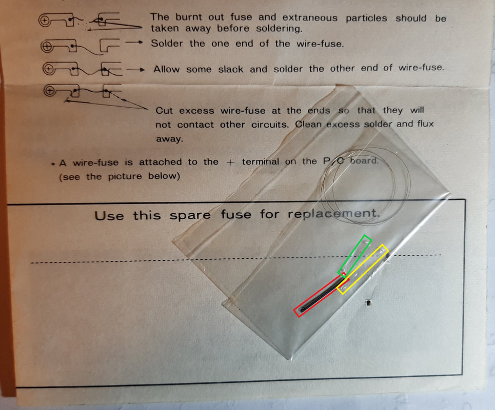
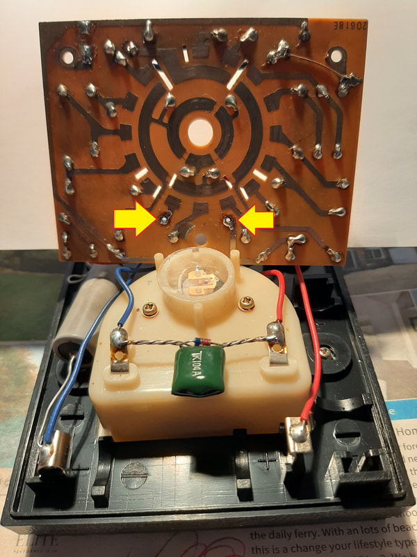
Perhaps to lower the price, Hioki have foregone the sophistication of a separate mounting for a fuse catridge, and have opted for the simple method of soldering some fuse wire across a gap in the circuit board's copper tracks.
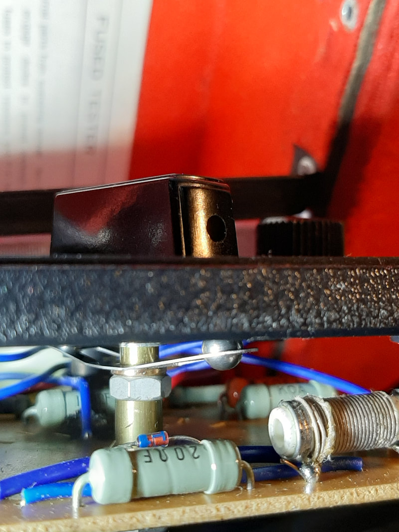
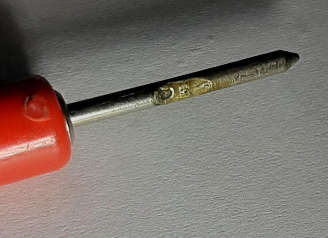
They are once again helpful by including a sheet separate from the manual, just to document the fuse wire location (See Left). They also helpfully supply a small coil of spare fuse wire. (Note the staple holes outlined in green.) I find the little plastic bag containing spare fuse wire has one large staple (red) , and two other sets of staple holes, one large (yellow), and a small set (green) which matches the holes noted above, probably the factory ones. I think we can conclude the fuse has been blown at least twice before. When we look at our fuse location, we can see that the soldering is not quite as neat as that achieved in adjacent locations by the the nimble fingers of a young Japanese factory worker, and also that the screw (which also serves to mount the board) has some highly suspicious melt damage. It seems that although this fuse has previously blown, it wasn't effective in protecting our resistor. There is a real puzzle here which I can't explain. I don't know how this tiny fuse wire could pass enough current to allow the screw to be melt-damaged and the resistor to be blown like a fuse. There is more evidence of some past incident when we examine the positive test probe, which also shows obvious melt damage. This kind of damage comes from either mains power or connecting directly across a large battery. I would guess the latter, as I know I have used the meter with car problems in the past. I believe I have replaced the fuse after the resistor was blown, but because I have subsequently only used the meter to check for continuity, that is, near enough to zero resistance, I haven't noticed that it was reading low. |
Repairing the fault
How the switch wiper arm is attached
Releasing the switch wiper arm nut
Cct board raised to show "top", with burnt 100Ω resistor bent away from board for access
Circuit board clamped for unsoldering
Cct board under, resistor unsoldered, holes clear
Cct board top, resistor gone, holes clear
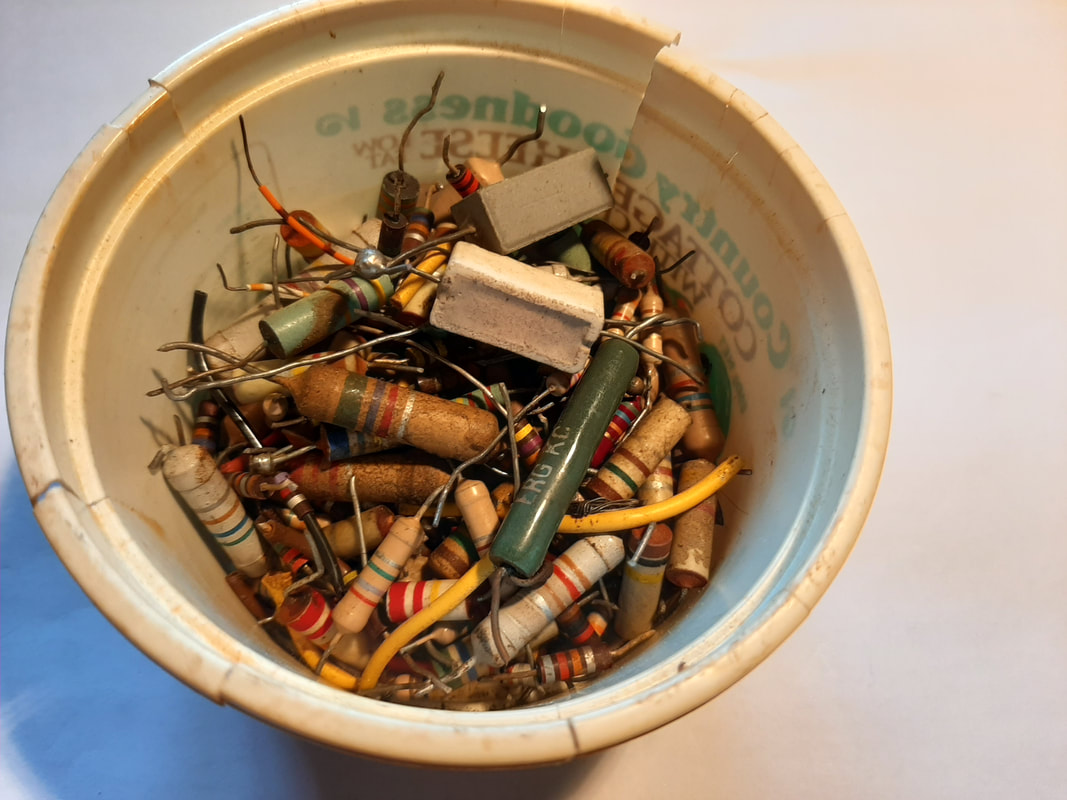
Scavenged resistors, forty-plus years old
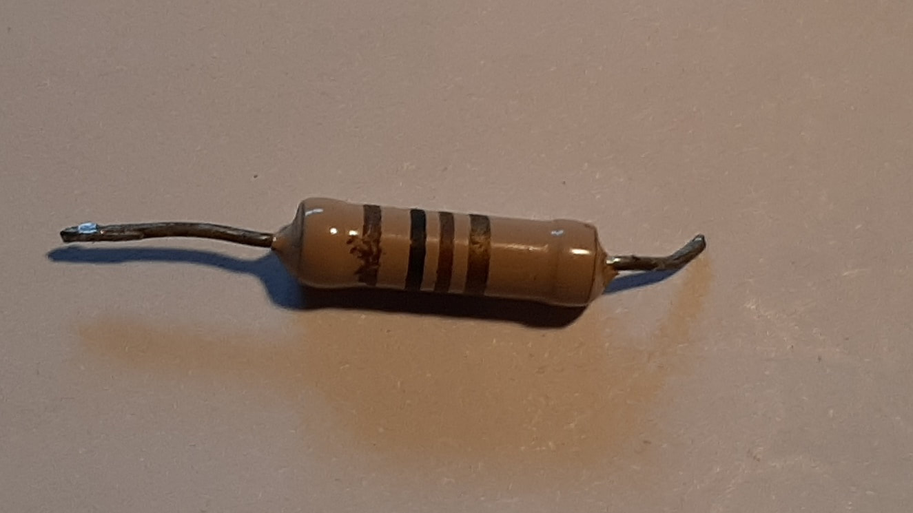
I found this scavenged 100Ω resistor. Brown, Black, Brown, plus Gold (5%) tolerance
|
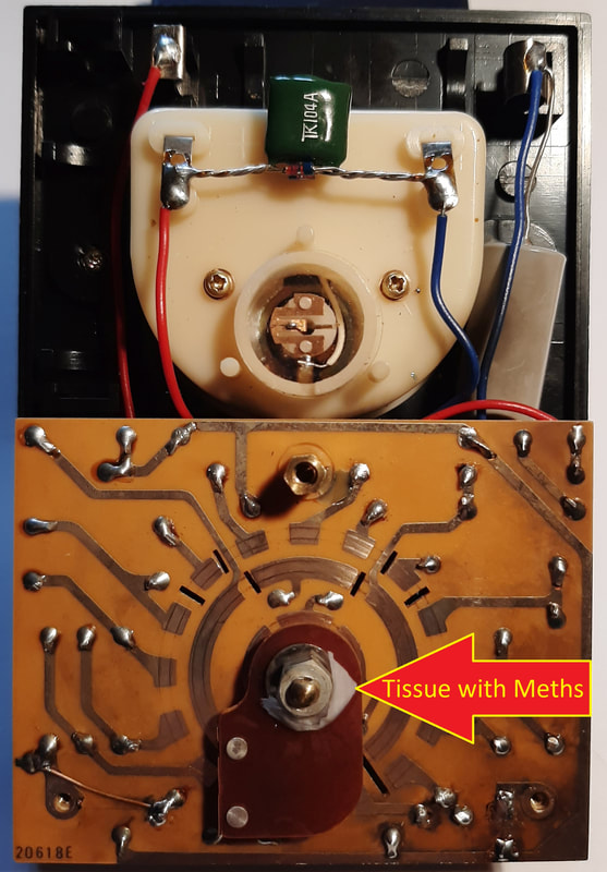
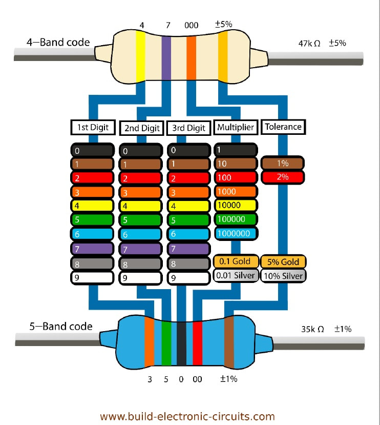
Having satisfied ourselves that we have found our fault, its cause, and that it is likely limited to this one part, we can steel ourseves to begin disassambly and repair. The first challenge is removing the switch wiper without damaging it, as we find the nut holding it to the shaft has been glued to stop the wiper shifting. This is in addition to the fastening method designed to keep the wiper rotating with the shaft by making the shaft flattened on both sides and giving the wiper a rectangular rather than round hole for the shaft end. We must hope this glue does not prove too good at its job! A first approach is softening the glue with a solvent. We are in luck, as a quick rub with a finger wet with methylated spirits produces a distinctly tacky feel. We now have a suitable solvent, first try. A small piece of paper tissue soaked in meths snugged up against the nut, and a few drops in the gap between the shaft's flat faces and the nut, soon have the glue softened, and the nut is easily unscrewed. Next we remove two mounting screws and a small brass pillar which both holds the board and takes the screw holding the back on. We are now free to lift the board, and have the access we need to the damaged resistor. We can also see that we are dealing with a pretty simple assembly here, an economical design considering what it does. The resistor has been bent to one side to clear the adjacent pillar holding the board clear of the face, and must be straightened to make removal easier. There is a splat of vapourised carbon on the board which could form a short circuit, but evidently hasn't, or the resistor would not have measured open circuit. The loose dust can be wiped off anyway, just in case. (Note: we can see the detent mentioned previously much clearer here.) Soldering is a two-handed operation, Our next step is to find a way to hold the board fixed without having to completely disconnect it from the rest of the Multimeter. I used a locking vice grip to hold onto the board, then a small table mounted hobby vice to hold the board and vice grip steady. It is not sufficient simply to melt the solder and pull the resistor leads from their holes in the circuit board (See Left). We must also remove as much surplus solder as possible, so that the hole is clear for the insertion of the new resistor leads and there is room for a nice fillet of new solder between the leads of the new(ish) resistor and the copper of the board's circuit layer.. At Left we see that the desoldered holes are also nicely clear from the component side, which should also be free of any surplus solder. At Left we see that the removed resistor was indeed one of 100Ω resistance, and the full extent of the damage on the underside we couldn't see before. A replacement resistor is now needed. In the dim, dark recesses of my mind there exists the memory of a drawer of scavenged parts in the dim, dark recesses of my garage, under the house. Quickly unearthed is the dairy product container at Left. These resistors must have been scavenged any time between 1975 and 1990 at the latest, but the equipment they came from, such as old radios or TVs, could easily be up to forty years older than that! But which one do we need? For the ininitiated this may seem a problem, but fortunately the little coloured stripes on the resistors can be decoded into both a size of resistance, and a degree of accuracy to that claimed size (the "Tolerance"). Referring to the diagram at Left, we find that we can expect (most commonly) four stripes. Two stripes for a two-digit number, e.g. 27, one stripe to multiply the number by some order of ten, and one stripe for a tolerance, e.g. 5% or 10%. Thus, for our replacement of 100Ω we need: -
A few minutes picking through the resistors got me the one at left. To the eye it looks like Brown-Black-Brown-Gold. The leads are just long enough, the tolerance looks to be Gold, 5%, and it actally measured pretty close to 100Ω with my new digital meter. It could just be, that appropriately, this resistor is about the same age as the Multimeter we are repairing! |
A note regarding the resistor tolerance: -
The Multimeter is designed to allow for minor variations in the shunt resistors, say because of temperature or aging, and for differences in the tolerances between ranges, or from using different test leads, clips etc.. If we consult the circuit diagram at top of page again, we can see a zig-zag line with an arrow crossing it diagonally, labelled R18. The arrow represents that the resistor is adjustable. We can also see that any current from any of the shunt resistors must pass through R18 to get to the meter, which is shown as a circle with an arrow through it representing the pointer needle. With this design, if we connect our test probes directly together, a maximum current will flow to deflect the meter all the way to the right, where the scale indicates zero resistance. Then if the needle is not sitting at zero, we can adjust R18 by turning the little black knob (labelled Ω ADJUST) on the Multimeter face just below the meter until the current is deflecting the needle exactly to the zero mark. The user should remember to zero the meter at the start of any session, or whenever the Range is changed.
(I note the fancy new UNI-T digital Multimeter doen't even have this adjustment facility, instead advising in the instructions that at low resistances on the 200Ω scale, the resistance of the leads needs to be compensated for, and you should note the reading with the test probes connected together, and subtract that from the test reading you get.)
Replacement 100Ω resistor soldered in, top
Replacement 100Ω resistor soldered in, under
|
At left we see the new (old) resistor soldered in place, not looking too big, although it is slightly larger than the original. This is not a problem, as the size mostly reflects how much power a resistor can take, and too big is fine. Too small in some circuits could mean the resistor gets too much power, and could get hot, or even fail. And here at Left we see my nice new soldering of the leads to the copper circuit board. |
Testing the repair
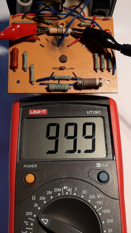
Replacement 100Ω Resistor measured in situ (0.1%)
|
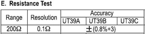
We're getting a bit "Meta" here, it's a Multimeter measuring a Multimeter. If we consult the Hioki's circuit diagram we can see that as long as the range selector is not set to "R x 1", there will be no other parts in parallel with R13. We can therefore rely on a measurement made by simply connecting my new digital Multimeter to the leads of the new 100Ω resistor. It is pretty satisfying to find we get a measurement of 99.9Ω, only 0.1% off the required value. Sounds good, but in fact, if we look at the specifications for the digital Multimeter: - we see that its Accuracy is plus or minus (0.8% plus 3 digits), thus even a theoretically 100% correct resistor of 100Ω could show as anything from 101.1Ω to 98.9Ω. I don't think it's possible for me to get a better result. |
Final Results
|
After reassembling the Multimeter I repeated the tests I did for the previous Multimeter comparison blog.
The results (Left & Below) were extremely gratifying. The Rx1 range is now returning readings under 2.5% different from the new digital Multimeter. The Ω ADJUST knob is now sitting slightly clockwise from where it was in the first pic of the meter at top of the page, this will be because our replacement R13 is slightly different from the original R13. There is slightly more difference in the voltage readings, but even there, the greatest is 4.7% on the Mains reading. I would rate this little Multimeter
still pretty much as good as new. Not bad for an instrument over forty years old! |
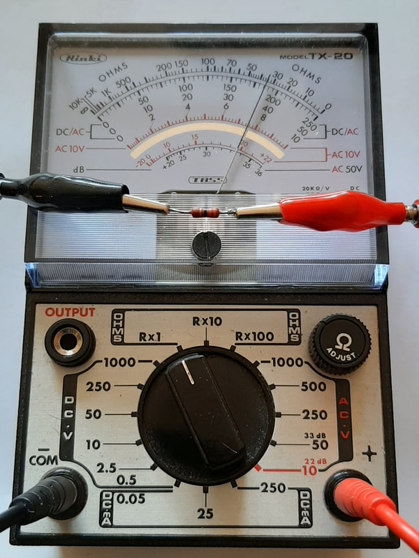
Multimeter repaired measures 33Ω
Multimeter repaired measures 390Ω
|
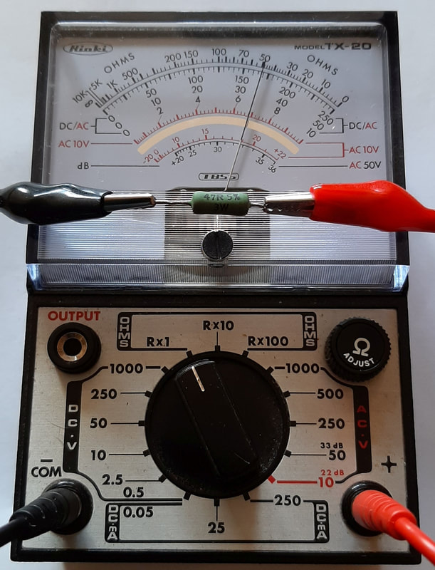
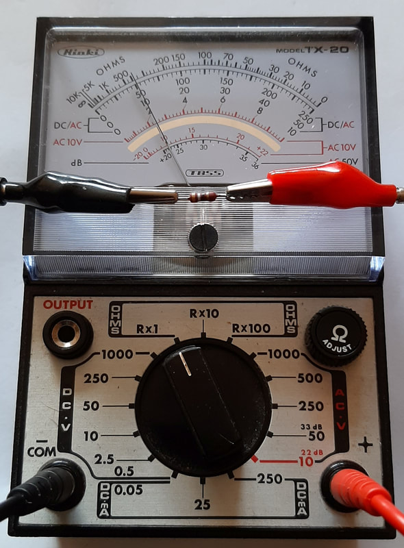
Multimeter repaired measures 47Ω
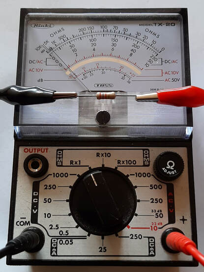
Multimeter repaired measures 2.7kΩ
|
