Making Up a Guitar Pedal Cable
06/09/2020
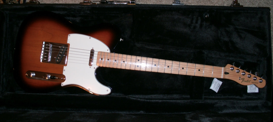
Fender Standard Telecaster, Maple Neck, Brown Sunburst
(FEN0145102532)
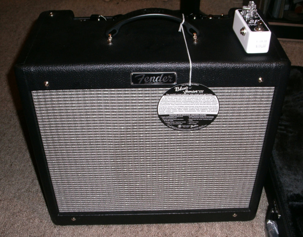
Fender Blues Junior III - 15 Watt All-Tube Amplifier
(FEN2230503000)
|
Back in 2016 I posted a blog page featuring things from the year I was born:1951. The very first item was the Telecaster electric guitar, a model introduced that year by Fender and still in production today. Examples of that 1951 model are far too expensive for me, but about 18 months later I finally splashed out and for the very first time in my life bought a brand new electric guitar, together with a new amplifier for it. ( See Left),
On the top right of the amp is a small white box; the XOTIC SP Compressor Pedal ($289) which I got at the same time. I already owned two good-quality cables, and could connect from the guitar to the pedal, and then from pedal to amp. However, for maybe 30 years I have also owned a DOD FX50-B overdrive pedal. This meant I needed a third, short cable to connect the two pedals. (Amazingly, I find the FX50-B is still selling as "vintage" for around NZ$100. Demo on YouTube.) A heavy-duty pre-made cable, at $35.00 isn't really necessary as I'm not a professional player. I bought the parts and made one myself. It wasn't really about saving money, I just made it because I can, and because I enjoy exercising the skill. However, at $12.48 it did prove to be about 1/3 the cost: - Plugs x2 @ $5.90 each, Cable 1m @ $3.40/m, 20cm = 68c. Then, the other day I used a gift card from work to buy a Boss TR-2 Tremelo pedal. Now, to add it to the chain, another short cable is needed. It only required two new plugs, as I still had 90cm of cable left (Yes, they really do cut you some slack!). It occurred to me that not everyone has learned how to make up a cable like this. I resolved to document the process. |
Below is what's involved in making up a cable.
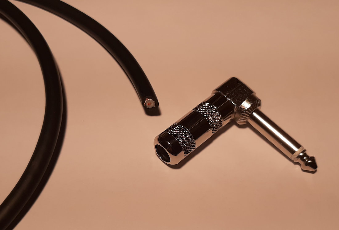
Cable and plug - as bought
|
Parts Required
Two 6.5mm Phono Right Angle Plugs (1/4 inch actually!) 20cm of Single Core OFC* Screened Audio Cable * OFC = Oxygen Free Copper, a bit of technical woo which makes no difference at 20cm lengths. The cable and plugs must be fairly robust, they will get more handling than a cable at the back of a domestic computer or audio/video system, for instance. Plastic plug covers are best avoided. |
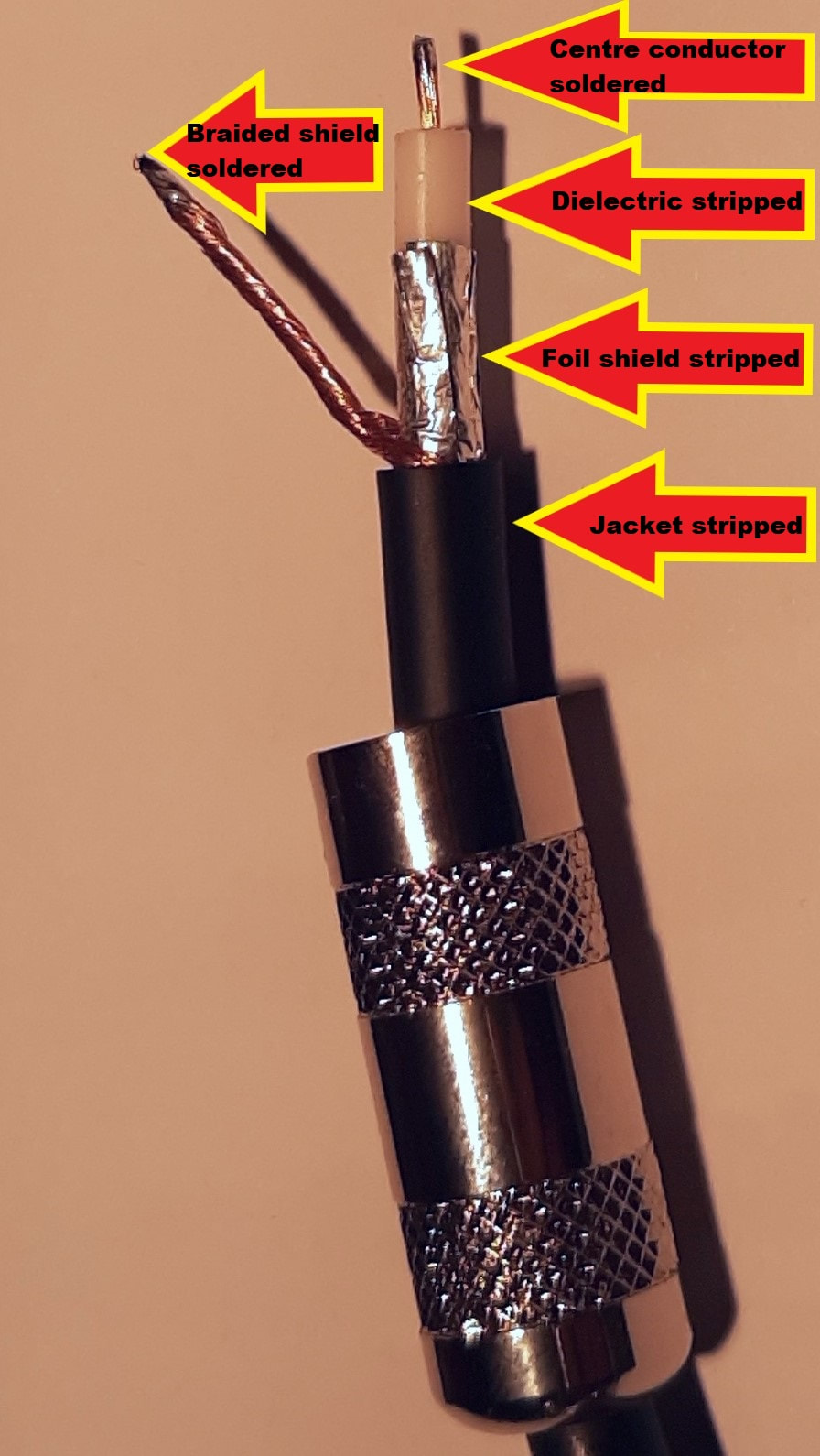
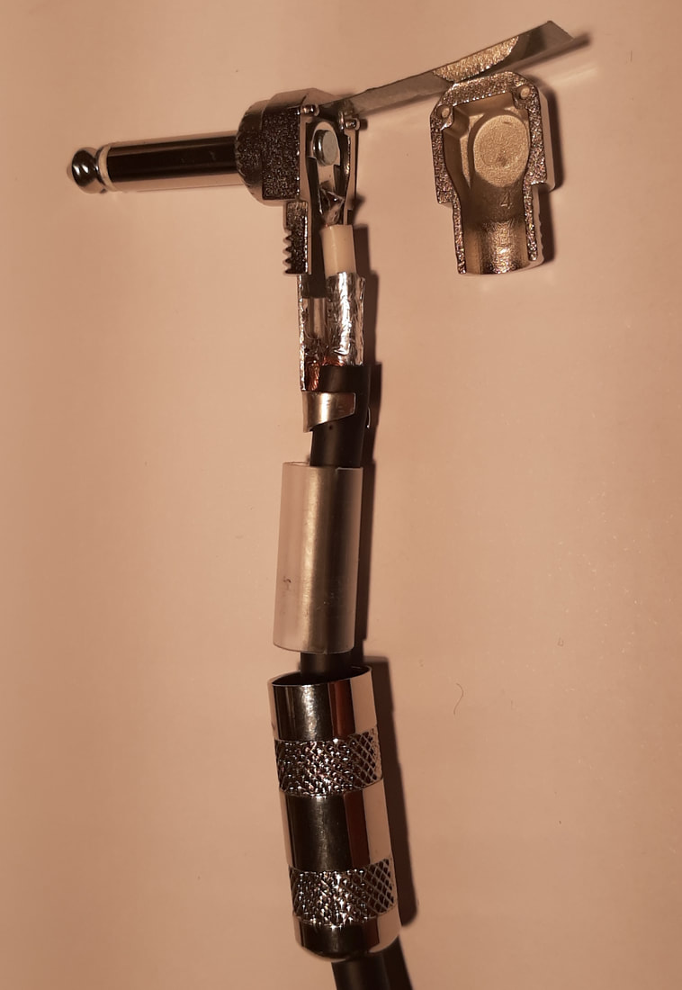
Cable stripped & tinned
|
Phase One one of the process:
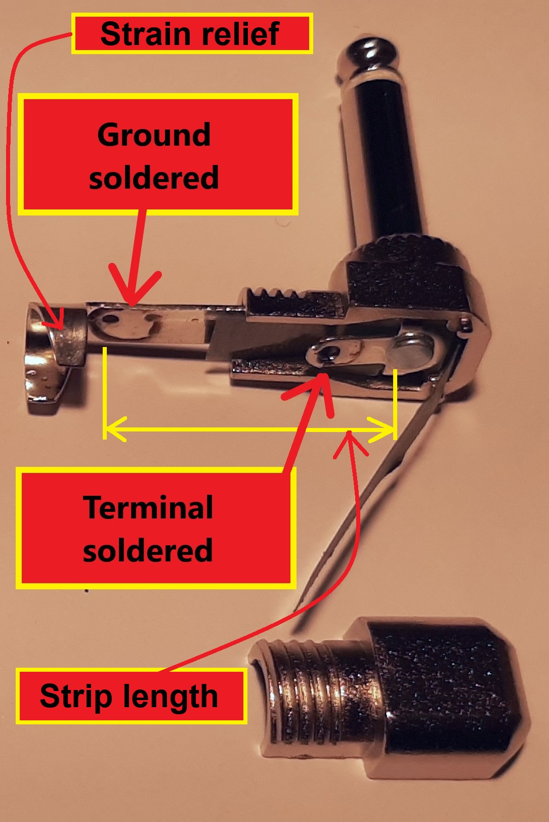
Preparing the ends of the cable. It is important to remember to put the plug covers onto the cable first! They won't fit over the plug when you've finished! I usually slip them on and tape them together to the middle of the cable, out of the way. The cable must be stripped back working inward through the layers, taking care not to damage an inner layer while cutting off the outer one. Mark on the jacket the length to strip (See Below Left), measuring from a few mms inside the strain relief which must grip the jacket, to a few mms past the hole in the terminal, which allows for enough bare centre conductor to bend through the hole. Carefully make a ring cut in the jacket at the marked length. If it is made nearly through the jacket, bending the cable slightly will tear the last part, without any danger of damaging the braid underneath. Slip the cut jacket off. Unbraid the exposed shield wire so as to bring all strands to one side of the cable and twist them together ready for soldering. A good point to consider here is the natural curve of the cable. We want the finished cable to sit with the plugs pointing outward. The ground terminal will be on the outside, so we should split the braid on the inside of the cable's curve and twist it together on the outside. Strip the foil shield next. We want as much as possible of the centre conductor's length shielded, but we don't want any risk of the shield touching the conductor. A few mms back from where we strip the centre conductor will do. The foil is a spiral wound ribbon of aluminium. A nick in its edge will allow a practiced hand to just tear it right around. |
Strip the dielectric from the inner conductor with care. A mistake now means stripping the whole cable back a few mms and starting again. Expose enough length of the copper to be theaded through the hole in the plug's centre terminal and then bent back to provide mechanical strength. Try not to splay the many fine wires too much, as we want them to sit as close together as possible for the next operation, so that the conductor will fit into hole in the plug's terminal.
To ensure a good soldered connecton to the plug, pre-solder the centre wire and shield wire ends. This is called "tinning", from the fact that solder is made by alloying (mostly) tin with (formerly) lead. Nowadays people run screaming at the mention of lead, and other (less satisfactory) metals are used with the tin instead.
To ensure a good soldered connecton to the plug, pre-solder the centre wire and shield wire ends. This is called "tinning", from the fact that solder is made by alloying (mostly) tin with (formerly) lead. Nowadays people run screaming at the mention of lead, and other (less satisfactory) metals are used with the tin instead.
Plug tinned
|
Phase Two: Preparing the plug for
terminating the cable. Get a soldering iron with the right amount of heat. The strain relief/ground connector will suck the heat from a small soldering iron used for circuit board work, and it won't be able to heat the connector enough to melt the solder. At least not quickly enough to avoid sending too much heat towards the plug sleeve, where there will be insulation between sleeve and inner conductor to the tip connector, most likely plastic, which could be melted. Too large an iron could also present the same risk. Quickly heat the terminal with a tinned tip of the iron, and apply solder to the terminal, only until it can be seen melting and flowing onto the terminal surface. This flow phenomenon is called "wetting", and is required to get a good physical and electrical connection. Apply only a minimum, sufficient to thinly coat the terminal, and not a giant blob which may obscure whether the terminal is actually wetted, and may drip and/or cause a messy short-circuit. Wet the strain relief/ground as well. Some brands have a hole for the wire, wet around that.Others just rely on soldering the braid to the flat surface at a suitable spot. Use the inner surface, as connecting a wire to the outer surface can prevent the cover from fitting back on. This particular brand has little insulating covers inside the plug which should be treated gently to avoid damaging them. They are a good feature, not a lot of plugs have them. |
Cable and plug - cable terminated
|
Phase Three: Terminating the cable.
Not having four hands, I use a dedicated soldering aid, something like this, with a clip to hold the cable and a clip to hold the plug, leaving the right hand for the iron, and the left to hold the solder. Needle-nosed pliers are also useful for bending wire and placing it in position. Solder the braid first, this avoids handling the work with only the more fragile centre conductor soldered. Align the braid end pointing towards the strain relief. This allows it to be curved around to enter the jacket without a tight bend. Ensure the tinned braid end sits unsupported closely aligned with and touching the tinned area on the strain relief, or try some arrangement that holds it in place with positive pressure. This ensures it will not tend to move while soldered. Then heat the strain relief while touching a little solder to the braid. When this solder melts, we know all the solder from iron tip, to strain relief tinning, to braid tinning, to solder applied has melted, and we will have a good, solid and continuous join. Ensure the iron is removed promptly without disturbing the area soldered. If things are moved while the solder is still melted, it will crystallise, resulting in a weak and poorly conductive joint. |
Manoeuvre the braid and jacket to sit within the arms of the strain relief, and clamp the cable and plug to align the centre conductor close to the terminal. Using pliers, bend the centre conductor to an L shape, then slip the end into the terminal hole. Bend the conductor more, into a U shape, then crimp the U onto the terminal. This will provide a good connection even without solder.
Following the same procedure as before, heat the terminal while applying solder to the wire, until the solder melts and there is a continuous area of melt from iron to solder.
After a visual inspection for any loose ends, solder splashes etc., physically align everything to make sure there will be no contact with the terminal except by the inner conductor.
Crimp the strain relief arms around the cable jacket with the pliers. This ensures any tension on the cable doesn't strain or fatigue the connection, principally the thinner, more fragile inner conductor.
Put the little inner insulating covers in place, add the cap, slide the cover's inner insulating sleeve over the whole termination area, then slide up and screw on the cover.
Phase Four: Repeat for the other end.
Phase Five: Testing the Cable.
Test that there is continuity from plug tip to plug tip, and from plug sleeve to plug sleeve. Then test that there is NO continuity from plug tip to plug sleeve.
Completed cable
|
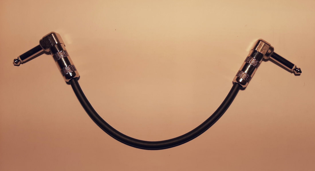
Phase Six: Cable completed. No loose ends, no frayed ends, no melt marks on the cable, and the plugs sit naturally aligned to their position in use. |
Cable plugged in - ready to go
|
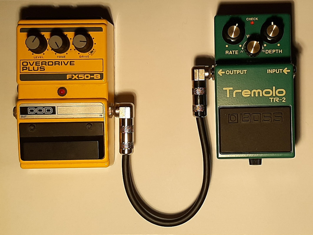
Phase Seven: Use the cable. Here, at Left we see a cable set up as it is used. |
The timestamps on my camera files show I can safely assert that this process
took me exactly 59 minutes, including time to stop and take the pix.
took me exactly 59 minutes, including time to stop and take the pix.
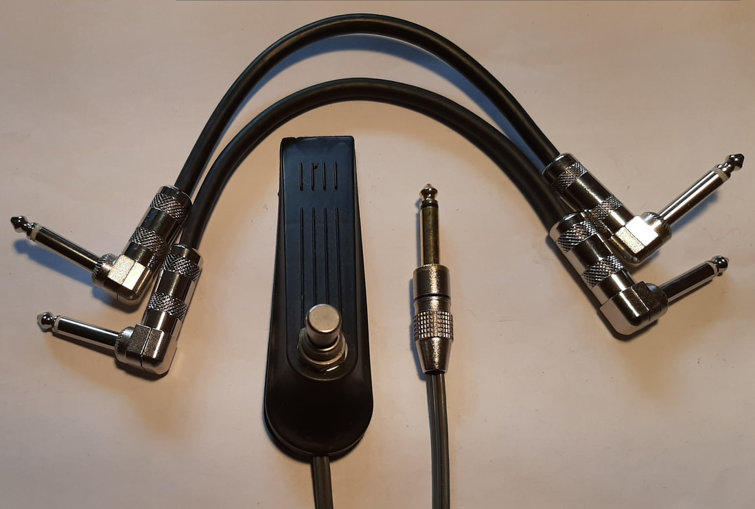
Two cables & footswitch
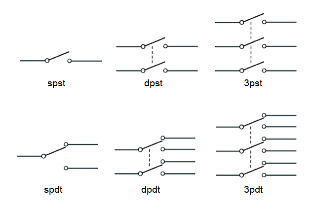
Switch Pole Arrangements
|
My current set of
home-assembled accessories. Here we see at Left a newer pic; two pedal cables and a foot switch. I will confess that money was a consideration when I made up the foot switch back in about 2017. That is, I couldn't believe how much they wanted for a device which would be a cable if it was any simpler! $59.00 for this famous-brand one. (See Below for how simple it is.) I put mine together for under half that: - 3PDT* Latching Foot Switch $18:90 Figure-8 speaker cable lying around Door Stop set of 3 from $2 Shop 6.5mm Mono Plug approx. $5.00 Total $26.00 *3PDT = Three Pole, Double Throw; a bit of overkill for an on-off switch, but it was all they had. (See below). The Footswitch
The Blues Junior amp has a switch labelled "FAT" on the top panel which is for quickly changing the input volume and tone by a small fixed amount. It also has an input socket at the back where you can plug in a cable to control the FAT function with a foot switch. All it needs is a two-wire cable, ends connected (Fat "on"), or not connected (Fat "off"). For that function we only need the very simple switch shown at Left, the Single Pole, Single Throw "spst" switch. The "3PDT" switch I bought can move three wires at once to connect to either of two other sets of three wires. Now you can see why a Three Pole, Double Throw switch is 4 1/2 times overkill for this foot pedal. |
Note that the 3PDT switch is lot dearer than the plug. An SPST switch would still be a similar price. This is because they are both "Latching", i.e. incorporate a locking mechanism, so that one push turns the swich on and it locks on, then another push turns it off, and it locks off. It is more expense to make and assemble the little springs and levers to accomplish this than it is to add poles.
